|
|
|
| Prototyp : Model : Jaguar XJR-10 / 11 |
|
Process, Part Three.
Introduction - 1 2 |
|
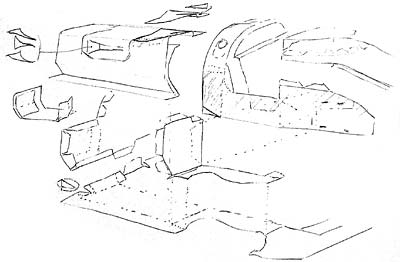
A conceptual sketch is done to visualize how the complex forms of the car's chassis might be broken down into individual parts. Small parts are kept to a minimum and as many parts are attached to one another in order to keep building simpler and alignment consistent. Gluing tab placements and the order of building steps are also considered.
|
 |
|
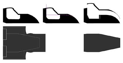
The technical illustrations are disassembled now. Individual panels are modified so that their angles in three-dimensions will accurately reflect the 2-dimensional specifications. The panels are arranged to fold and glue as determined in the conceptual sketch above. Here the central undertray, side pods and front and rear bulkheads are layed out on a printable page. |
 |
|
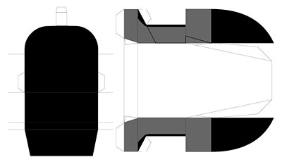
Major tub panels are isolated from the technical illustration. The portions of the sides of the tub which angle in toward the centerline (when viewed from above) are lengthened. |
 |
|
The tub's core panels arranged and ready to print. This the basic inner shell of the tub. Combined with the sidepods and rear bulkhead, the chassis will more accurately depict the car's design. The Jaguar was unique in that it was one of the few cars to utilize a full "unibody" chassis rather than a narrow central tub with separate side and nose structures. |
 |
|
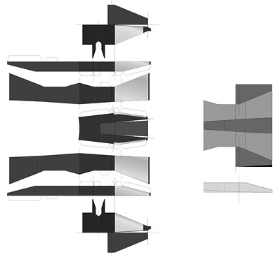
The rear undertray parts and their source illustration. |
 |
| The built chassis and tub > > |